The bulk of our efforts toward the goal of interoperable meshing and discretization software in the first year has focused on the development of a common interface for mesh geometry and topology access, and we describe these efforts below. To ensure that our tools are as broadly available as possible, we have worked closely with the Common Component Architecture (CCA) forum to investigate the use of their SIDL/Babel language interoperability tools and to ensure that our interfaces will be compatible with the CCA component specification. Finally, to demonstrate the promise of interoperable tools, we have been working to merge two TSTT tools, Overture and Frontier, to create a powerful simulation tool that combines adaptive mesh refinement and front-tracking techniques.
Common Interface Definition
One of the primary development efforts that showcases TSTT teamwork is our creation of common interfaces for mesh geometry and topology access. Our philosophy has been to focus primarily on the definition of accessor interfaces that provide the functionality needed by application programmers. A key aspect of this approach is that we do not enforce any particular data structure or implementation with our interfaces, only that certain questions about the mesh (such as geometry or first-order adjacency information) can be answered through calls to the interface. The challenges inherent in this type of effort include balancing performance of the interface with the flexibility needed to support a wide variety of mesh types and the desire to keep the interface minimal so that it is easy to implement and adopt.
Data Hierarchy Concepts
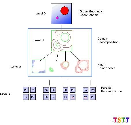
Meshing and discretization technologies must take into account a conceptual hierarchy of domain representations (see Figure 1). The original problem specification can be given in terms of a high-level geometric representation such as a CAD description, image data, or possibly a previous mesh, along with the physical attributes of the application (level 0). As an example, the electromagnetic simulations for accelerator design are based on a detailed and complex specification through CAD-generated geometries, while for other applications such as plasma physics, typical input geometries are relatively simple. This geometry has a global representation of some kind (such as a non-manifold solid model or pixel intensity information) that properly represents the physical domain. The geometric model can be decomposed into sub-regions (level 1), each of which could be discretized using a possibly different fundamental mesh type. Decompositions for the purpose of adaptive mesh refinement must also refer back to the original geometrical information, and hence are part of this level. The next level (2) consists of the meshes that are constructed within the components of the level 1 decomposition. Because the simulations will be run on terascale parallel computers, a further decomposition (level 3) to support the partitioning of the levels 0-2 entities across the 1000’s of processors involved is defined (see the Terascale Computing Section). All the levels shown in Figure 1 can be considered different resolutions of the domain, and fit into a hierarchy of representations. Meshing and other tools (e.g. for partitioning, discretization, or solution interpolation) can access these representations through a common interface, simplifying the process of changing the resolution either inside a level or between levels. The use of this concept will be explored using the various representations available in the Common Geometry Module (CGM).
Figure 1. Domain Hierarchy
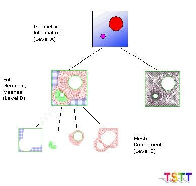
Analogous to the conceptual geometry hierarchy discussed in the previous paragraph, we also focus on a mesh data hierarchy (Figure 2). The highest level in this hierarchy (level A) again contains a description of the geometric domain. Access to this information is provided, for example, by generic interfaces such as CGM, direct functional interfaces to solid modeling kernels, e.g. [SheGeo92], or data file representations such as IGES and STEP. The lowest level (C) shown in the figure again represents the mesh components, while the intermediate level (B) represents the combination of the level C mesh components into an overall hybrid mesh, together with the communication mechanisms that couple their data together. In addition, level B allows the possibility of multiple mesh representations for the complete geometry to be used within a single application, or in coupled applications. At level B, code developers or users can access the entire grid hierarchy as a single object, and call functions that provide, e.g. partial differential operator discretizations, adaptive mesh refinement or multilevel data transfer over the entire mesh. This will be accomplished by providing an interface much like that currently provided in the Overture framework. Functionality at this level will enable the rapid development of new mesh-based applications. In addition to this high-level strategy, we also provide access to the hierarchy at low levels to facilitate the incorporation of our tools into existing applications. At level C, for example, we will provide access to Fortran-callable routines that return discretization or interpolation coefficients at a single mesh point or array of points on a mesh. Initially access at these lower levels is likely to provide for more efficient implementations. However, we expect that by basing the higher-level tools on highly optimized kernels, both code development and runtime efficiencies will ultimately be realized.
Figure 2. Mesh Data Hierarchy
Interface Definition Efforts
As of September 2002, the TSTT interface definition group has agreed to nomenclature regarding mesh entities and basic functionality for accessing geometric and topological information about the mesh. In particular, the TSTT interface supports topologically-dimensioned entities which are called VERTEX, EDGE, FACE, and REGION for 0-3D respectively. Each of these entities can live in a geometric dimension equal to or greater than its topological dimension although we assume that the geometric dimension is the same for all entities in a given mesh. In addition, various topological regions are supported; in particular, TRIANGLE, QUADRILATERAL, and POLYGON are supported in 2D and TETRAHEDRON, HEXAHEDRON, PRISM, SEPTAHEDRON, and POLYHEDRON are supported in 3D. Access to the mesh geometry and topology information is provided through a number of different mechanisms. For example, care was taken to ensure that access to coordinate and adjacency information in the mesh was provided on both an entity-by-entity basis by using iterators of opaque objects and for the entire mesh at once through arrays of doubles. All implementations are required to support both modes of access although it is recognized that only one style is typically native to the underlying implementation thus may require a copy operation if the other mode of access is requested. To improve performance of the entity-based functions, a workset iterator interface is provided that allows the user to request entities in an array of a user-specified size (for example, 100 entities at a time). These arrays can then be used in any of the entity-based function calls to retrieve large chunks of information to minimize the number of calls through the interface. Additional functionality that is currently supported for the mesh includes mesh creation, loading, destruction and services to access basic information such as its geometric dimension, the number of each type of entity, etc. Finally, the user is able to attach an arbitrary piece of data to any mesh entity or to the mesh itself through the use of tags. This allows the interface to become useful to application scientists by providing functionality for attaching boundary condition information, material properties, etc. In total, this interface contains 39 functions and provides the functionality needed to support a basic mesh-based simulation. More information on the TSTT interface specification can be found on our software web page.
Implementations of this specification are underway at LLNL (for Overture), PNNL (for NWGrid), RPI (for AOMD), SNL (for MDB/CUBIT), and ANL (for a simple triangular mesh). Additional efforts that use the interface for interoperable meshing technologies are ongoing at SUNY SB as part of the Frontier merge with various TSTT mesh generation technologies and as part of the MESQUITE mesh quality improvement toolkit.
In addition to the basic interface specification described above, a number of additional functionalities have been discussed and the interface definition efforts for them are well underway. In particular, we are considering the addition of
- mesh sets that allow arbitrary groupings of mesh entities,
- submeshes that support the mechanisms needed in an interoperable meshing environment such as parent child relationships among meshes as well as data transfer among meshes,
- parallel queries to support distributed computing, mesh modification interfaces to support adaptivity, and
- fields and degrees of freedom managers to support the development of the TSTT discretization library.
Use of CCA Technologies in the TSTT Interface Definition Efforts
Throughout the first year, the interface definition group has worked in conjunction with the Common Component Architecture (CCA) Forum in a number of ways to ensure that the TSTT interfaces are compatible with CCA specifications. Our efforts fall into two major categories.
First, we have done a significant amount of work to understand and use the Scientific Interface Definition Language (SIDL) and associated Babel compiler developed as part of the CCA effort. This work is motivated by the fact that many of the TSTT tools are written in C++ and most of our targeted applications are written in Fortran. We did not wish to settle for the least common denominator solution of using arrays for all of our data transfer. Thus we are using the SIDL tool to define our interfaces in a language independent manner and to facilitate the consistent and efficient implementation of language bindings to these interfaces. In particular, we have generated and used the C, C++ and Fortran bindings for various TSTT mesh implementations. In addition, LLNL has created a prototype interface for fields and operators using SIDL. To help all TSTT sites incorporate SIDL as part of their everyday work environment, Kyle Chand (LLNL) has developed a simple SIDL tutorial that incorporates a simplified version of the TSTT interface and has distributed this tutorial to TSTT researchers. Ongoing work is being performed to clearly understand the performance ramifications of using SIDL/Babel, particularly on fine-grained operations such as entity-by-entity access to mesh geometry and topology. In particular, we are investigating the possibility of providing language- or tool-specific access to the underlying meshes for the cases where high performance is critical for this type of access. Early efforts include a development of a C++ version of the TSTT interface that bypasses the SIDL intermediate object representation (written in C). However this work is very preliminary; much more needs to be done to evaluate the performance ramifications of SIDL on our interface and to develop solutions that are compatible with the SIDL specification (currently planned for year 2).
Second we are developing TSTT and CCA-compliant mesh components and using them with other numerical components to demonstrate their ability to solve application problems. The first application involves a two-dimensional TSTT mesh that was used in conjunction with time integrator, linear solver, MxN redistribution, and visualization components (all developed at different labs as part of the CCA Forum efforts) to solve a time dependent PDE in the CCAFFIENE framework developed at SNL. This work was demonstrated at SC01 and continues to be used to illustrate complex application scenarios in the quarterly CCA tutorials. The second application was developed using the NWGrid meshing software from PNNL. In this case, a SIDL version of the TSTT interface was used to generate a Fortran binding for NWGrid so that it could be used with a mesh quality improvement component (based on Opt-MS algorithms from ANL) that was written in C. These components were successfully deployed and used in the DeCaf framework developed by LLNL.
TSTT Tool Interoperability: FronTier and Overture
To showcase the potential payoff for an environment that supports interoperable meshing and discretization software, we have engaged in a few efforts that target one-to-one interoperability between TSTT tools. The most notable effort in this regard is the ongoing work to merge the FronTier front-tracking code with the Overture adaptive mesh management framework. FronTier (SUNY SB and BNL) has been used to apply the front-tracking method to different scientific problems such as gas dynamics, petroleum reservoir study, MHD and solid interface problems. Overture (LLNL) is a mesh management framework that has adopted the AMR method proposed by Berger and Colella to insert highly refined patches in regions where wave interaction demand increased resolution in the interior region. Our goal within the context of the TSTT center is to combine the strengths of the FronTier and Overture codes to develop a new, efficient front-tracking algorithm combined with the AMR technique, the so-called AMR Front Tracking Method.
This work was completed primarily at SUNY SB with help from the Overture team, and through the last year, this project moved through three phases. The first phase involved a complete understanding of the Overture algorithms and its implementation. This included understanding its objectives, the implementation of the relevant algorithms, as well as its data structures, functions, and the computational environment.
The second phase involved resolving the conflicting definitions and macros in the two codes. Because the two codes were developed independently, a number of conflicting definitions, function names and macros with identical names were used for similar (but not exactly the same) or different purposes. These conflicts were resolved by restricting most of the necessary changes to the FronTier code, thereby ensuring easy access to future Overture upgrades.
In the third phase, our objective was to construct a common interface for the communication of data in the two codes. The most difficult part of the work has been in the generalization of patch and subdomain communications. Although FronTier is parallelized, the data communication between patches inside the same parallel processor is outside of the development framework. As a result, we needed to find a practical method to synchronize the computation of different patches inside the same parallel processor. We finally decided to modify the entire functional structure of the interface propagation in the FronTier code to have it fully modularized at the synchronization points inside a single driver function. Figure 8 shows the adaptive patches with the tracked front.